Thursday, 29 January 2026
Alantek Continuity Wire Map Tester for UTP/FTP/COAX

Alantek Continuity Wire Map Tester for UTP/FTP/COAX
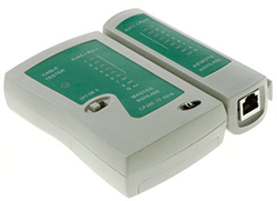
Continuity Wire Map Tester will check continuity in your twisted pair (RJ11, RJ12, RJ45) and coaxial (BNC) cables. It not only works as a continuity tester, it also indicates any potential problems via the LED's. Cabling faults such as continuity, open wires, shorts, mis-wiring and crossed-over pairs can be shown. The tester consists of a main Master unit and a detachable Remote unit, each of which have an RJ45 and BNC connecction. The unit is powered with a 9-volt battery (not included).
SRP: ₱ 4,500

Pay only P 423 a Month for 12 months.
Or pay only P 802 a Month for 6 months.
- Installment promo is available for locally issued credit cards
- Card holder must transact inside an Asianic store to avail of the installment
Features
1. Test continuity of twisted cables, like Cat3, Cat5e, Cat6 and Coaxial Cable.
2. Support connection of RJ11, RJ12, RJ45 and BNC.
3. 9 LED light on both master and remote to indicate to connection on PIN 1, 2, 3, 4, 5, 6, 7, 8 and Ground(Shield).
4. Can easily identify cable continuity, cross wire, open and short, up to 1000ft.
5. Auto scanning function for rapid testing.
6. Operate with one 9V battery
Package Includes
- 1 x USB LAN Network/Phone Cable Tester RJ11 RJ45 Cat5
- 1 x User Manual
Package contents
- Continuity Wire Map Tester
- Remote terminator
- Storage Case
Operation
Important warning: Never use the tester in the live circuits.
- Insert a 9V battery (* not included)
- Set the main switch into ‘ON’ or 'S’ (slow) mode. The power indicator should light up.
- Plug one end of the cable into the main tester
- Plug the other end of the cable into the remote terminator
- Switch the tester on (set it to 'On' for "Automatic Mode' or to 'S' for the 'Slow
Automatic Mode
The wires now will be tested one after another; the tester will switch from one wire to the other automatically. In this way, the wiring can be quickly checked on the display of the remote terminator indicators too.
If the cable is wired properly the indicators will light up synchronously in the following sequence:
Main tester : 1-2-3-4-5-6-7-8-G (RJ45)
Remote terminator: 1-2-3-4-5-6-7-8-G (RJ45)
- If the cable is wired in a wrong way the Test outcome indicators will light up in a different sequence, for example:
- Suppose wire number 3 is not connected to the remote side - in this case the Main tester third indicator will light up but there will be no light on the Remote Side.
- Suppose wire number 3 is connected to the wire number 5 of the remote side - in this case the Main tester third indicator will light up simultaneously with the Remote side fifth indicator.
- Suppose there is a short circuit between two or more wires. - in this case no lights will be up on the Remote side.
- If you test Coaxial cable, BNC indicator will be lighted up for the proper wiring
